Introduction: The Importance of Proper Wiring
Ceiling lights play a crucial role in illuminating our homes and workplaces, providing both functionality and aesthetics. However, installing a ceiling light requires a good understanding of wiring diagrams to ensure safety and proper functioning. In this comprehensive guide, we will delve into the intricacies of wiring diagram for ceiling light installations, empowering readers with the knowledge needed to illuminate their spaces safely and effectively.

Understanding the Basics of Electrical Wiring
Before diving into ceiling light wiring diagrams, it’s essential to grasp the basics of electrical wiring. Electrical wiring consists of conductors, typically copper or aluminum, enclosed in insulation to prevent electrical shocks and short circuits. Wiring circuits include hot wires (live wires carrying electrical current), neutral wires (return paths for current), and ground wires (safety conductors to prevent electric shock). Understanding these fundamental components is crucial for interpreting wiring diagrams accurately.
Components of a Wiring Diagram
A wiring diagram for a ceiling light installation typically includes several key components:
- Power Source: Indicates the source of electrical power, often a circuit breaker or fuse box.
- Switches: Represent switches that control the ceiling light, including single-pole switches, three-way switches, or dimmer switches.
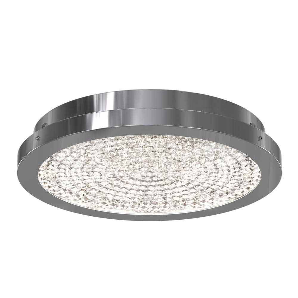
- Fixture: Depicts the ceiling light fixture, including the light bulb socket and any additional components such as a fan or integrated lighting controls.
- Wires: Illustrate the electrical connections between components, including hot wires (typically black), neutral wires (usually white), and ground wires (usually green or bare copper).
Understanding how these components interact is essential for correctly interpreting and implementing a wiring diagram for ceiling light installations.
Types of Wiring Diagrams
Several types of wiring diagrams are commonly used for ceiling light installations, each serving a specific purpose:
- Single-Pole Switch Diagrams: Used for simple on/off control of a ceiling light from a single switch.
- Three-Way Switch Diagrams: Employed when a ceiling light is controlled from two different locations, allowing for convenient access from multiple points.
- Dimmer Switch Diagrams: Utilized when a dimmer switch is installed to adjust the brightness of the ceiling light, offering customizable lighting options.
- Fixture Diagrams: Detailing the wiring connections within the ceiling light fixture itself, including connections for multiple bulbs, fans, or integrated features.
Understanding the type of wiring diagram required for a specific installation scenario is crucial for ensuring proper functionality and safety.

Safety Considerations and Code Compliance
Safety is paramount when working with electrical wiring. Before attempting any ceiling light installation, it’s essential to adhere to safety guidelines and electrical codes established by relevant authorities. This includes turning off the power supply to the circuit at the breaker or fuse box, using appropriate safety gear such as insulated gloves and goggles, and following manufacturer instructions and local building codes meticulously. Additionally, consulting a qualified electrician or professional installer is advisable for complex installations or unfamiliar wiring scenarios.
Step-by-Step Installation Process
A typical installation process for a ceiling light involves the following steps:
- Turn Off Power: Switch off the power supply to the circuit at the breaker or fuse box to prevent electrical hazards.
- Remove Existing Fixture: If replacing an existing ceiling light, carefully remove the old fixture, disconnecting wires as necessary.
- Prepare Wiring Connections: Strip insulation from wire ends and make appropriate connections according to the wiring diagram, ensuring tight and secure connections.
- Mount Fixture: Securely mount the ceiling light fixture to the ceiling or junction box, following manufacturer instructions.
- Test Functionality: Once wiring connections are made and the fixture is installed, restore power to the circuit and test the functionality of the ceiling light, ensuring proper operation.
- Final Adjustments: Make any final adjustments to the position or orientation of the ceiling light fixture as needed to achieve the desired lighting effect.
Following these steps systematically while referring to the appropriate wiring diagram ensures a successful and safe ceiling light installation.

Common Wiring Configurations for Ceiling Lights
In addition to understanding the basics of electrical wiring and the components of a wiring diagram, it’s crucial to familiarize oneself with common wiring configurations for ceiling lights. These configurations dictate how the electrical connections are made between the power source, switches, and light fixtures. Here are some of the most common wiring setups:
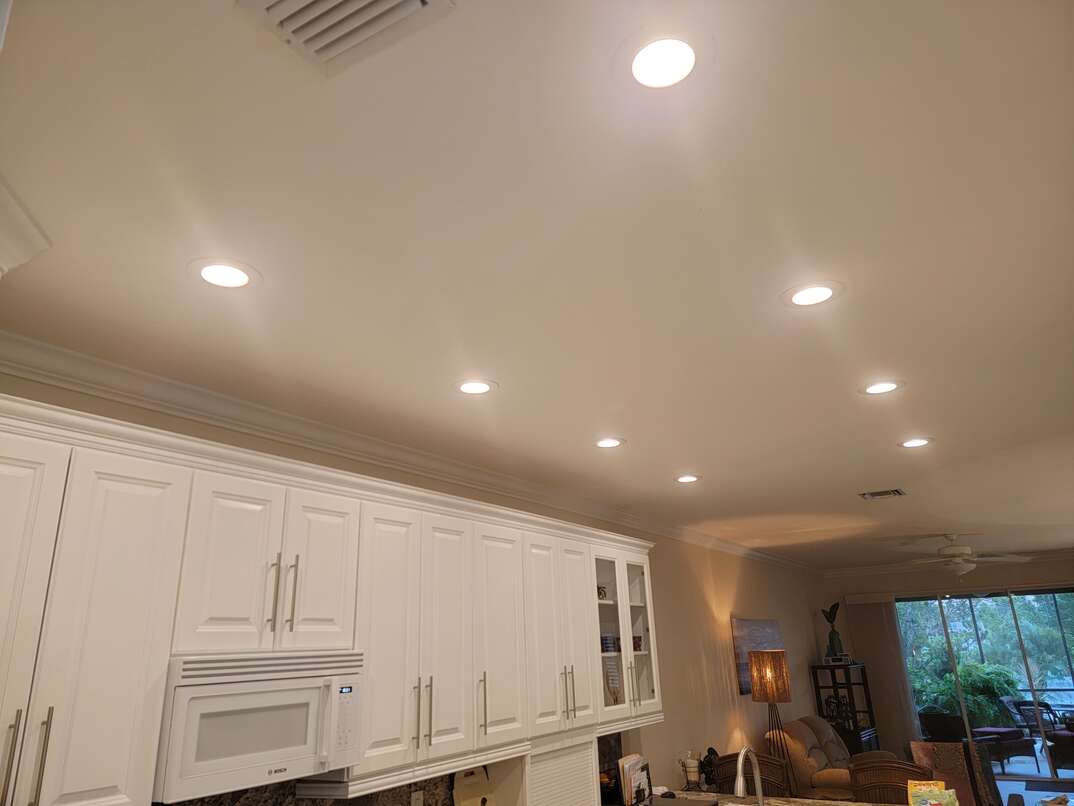
- Single-Pole Switch Setup: In this configuration, a single switch controls the ceiling light. The hot wire from the power source connects to the switch, and another wire runs from the switch to the ceiling light fixture. This setup is straightforward and suitable for rooms where only one switch controls the light.
- Three-Way Switch Setup: Three-way switches are used when you want to control a ceiling light from two different locations, such as at the top and bottom of a staircase or at opposite ends of a hallway. This setup involves two switches and requires additional wiring to create a circuit that allows for control from multiple switches.
- Dimmer Switch Setup: Dimmer switches provide the ability to adjust the brightness of a ceiling light, allowing for customizable lighting levels. Similar to single-pole switches, dimmer switches control the flow of electricity to the light fixture. However, dimmer switches are equipped with a variable resistor that regulates the amount of current passing through, thus controlling the brightness of the light.
- Multiple Fixtures Setup: In rooms where you want to install multiple ceiling light fixtures, such as in large living rooms or open-concept spaces, you’ll need to consider how to wire them together. This typically involves connecting each fixture in parallel to the power source, ensuring that they all receive power independently.
Understanding these common wiring configurations will help DIY enthusiasts and homeowners choose the appropriate wiring diagram and execute the installation correctly.
Conclusion: Empowering DIY Enthusiasts
In conclusion, understanding the wiring diagram for ceiling light installations is essential for DIY enthusiasts and homeowners looking to upgrade their lighting fixtures. By comprehending the basics of electrical wiring, interpreting wiring diagrams accurately, and adhering to safety guidelines and electrical codes, individuals can confidently install ceiling lights in their homes or workplaces. Whether it’s a simple single-pole switch setup or a more complex three-way switch configuration, proper wiring ensures safe and effective illumination of interior spaces. With the knowledge gained from this guide, readers can illuminate their spaces with confidence, transforming their environments with beautiful and functional ceiling lighting solutions.
